


In 1934, when Boeing decided to first use a Lycoming R680 engine on one of their airplanes, the engine had already been in production for nearly five years. In that short time Lycoming had already made several improvements to their original 215 hp engine, but all these were engineering changes that resulted in new dash numbered engines. It was not until 1937 that the first service bulletins were issued for the R680, data and design improvements intended to increase the engine’s reliability. During those dark days of the Great Depression when not many commercial airplanes were being built and military orders were scarce, the engine was not operated as much as it might have been otherwise. It would take WWII, with thousands of Boeing/Stearman Kaydets, Stinson Gullwings, and Beech AT-10s racking up thousands of flight hours, to thoroughly ring out the engine design and find maintenance issues needing correction.
The early service letters dealt not so much with safety issues or design problems, as with recommendations about engine operation and other minor issues: SB #4 authorized using a 4 degree staggered magneto spark for better mag checks. SB #7 gave us the fuel consumption of the various engines on the test stand. SB #15 listed the life expectancy of various internal engine parts.
One of the first major changes to the engine design came as a result of a military requirement that the engines of all training aircraft be altered in whatever way necessary to do away with oil changes between overhauls (oil would now have to be self-changing!) SB #110 dated 11/10/44 begins, “Inasmuch as Army Air Force Regulations would not permit an oil change between overhauls, it was found necessary to modify the Cam Assembly and Crankshaft Sleeve to obtain better lubrication for these parts due to accumulated sludge…” Different manufacturers had different responses to this new Army requirement. Jacobs increased their master rod bearing to crankpin clearance with the result that the engine could run effectively with much dirtier oil (with the wider clearances it also ran much hotter).
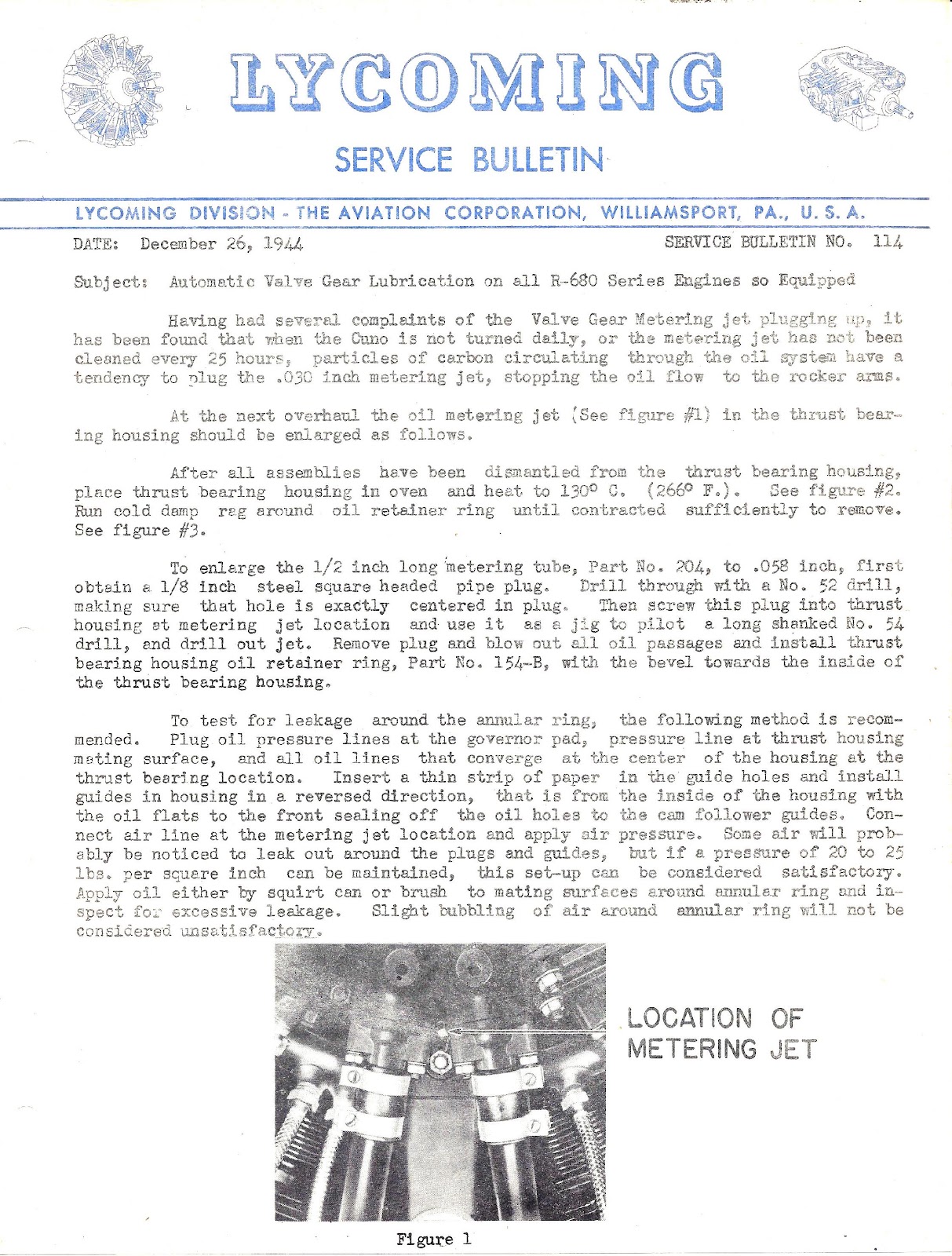
With only 25 hr. oil change intervals Lycoming was already experiencing problems with stoppages in their valve train oiling system, and a fix would need to be implemented if the break-in oil was to be run to TBO. Service Bulletin # 114 (see figure 1) recommended that the valve gear metering jet (located in the nose case behind an 1/8” pipe plug located just above the engine sump) be enlarged from .030” to .058”. With the original .030” hole, almost any piece of carbon or gasket material floating in the oil would stop the oil flow to the rocker arms.
We once had an engine in our shop that had run for many hours with the original .030” oil metering jet stopped solid with carbon. The rocker arm bearings in the #1 cylinder had ground themselves to dust and the rocker arms were rocking freely from side to side in the rocker box. The exhaust rocker arm had actually worn a hole completely through the side of the rocker box and would have created a real oil leak, had there been any oil in the rocker box to leak out!
The Army Air Force took the oil metering jet fix a step further in Technical Order No. 02-15AB-11 when they required that the jet be enlarged from .030” to .081”. This modification increased the upper cylinder oil flow by a factor of seven, and I have to admit that I have never seen one of the .081” holes clogged by anything!
Without a doubt, the most important service letter that Lycoming issued for the R680 was Service Bulletin #126 dated 4/1/46. This bulletin describes a modification so critical to the safe operation of the engine, and even today a modification that is so often overlooked, that I believe it should be an Airworthiness Directive. Figure 2 shows the full text of this bulletin.
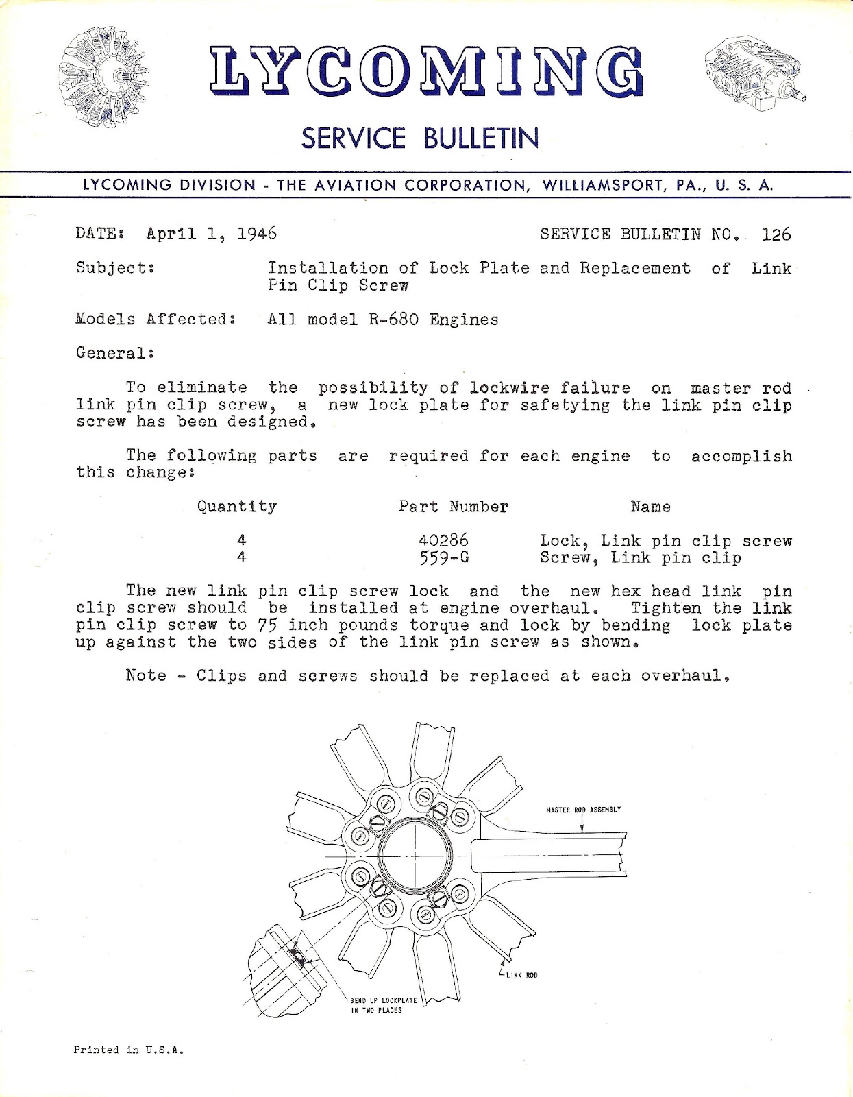
Figure 3 shows a Lycoming master rod assembly with safety wire between the lock plates on the right side of the master rod as was installed on all early engines, and the lock clips as on the left side per SB 126. This rod was assembled this way strictly for demonstration.
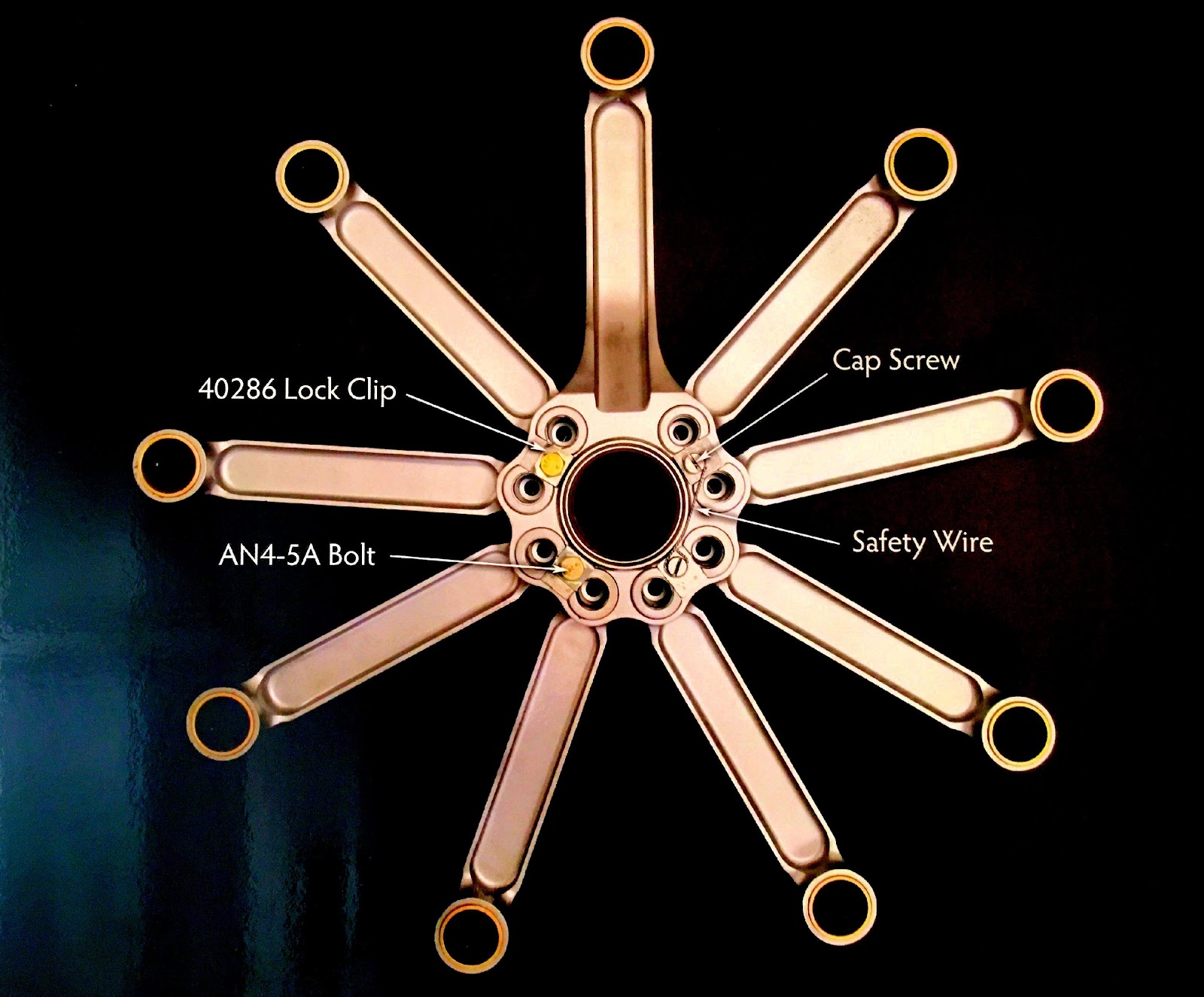
Figure 4 shows what is left of a master rod when the safety wire breaks, the knuckle pins back out, and the engine literally explodes. The engine in Figure 4 was operating at takeoff power and was a few hundred feet off the ground when this failure occurred. The master rod was wadded up and trapped between the engine power case and the crankshaft counterweight moving at 2300 rpm. The propeller stopped so suddenly that its inertia caused the crankshaft splines to twist about 30 degrees before snapping off just forward of the thrust nut. Fortunately, there was a bean field straight ahead and the pilot was able to make a suddenly very quiet, but safe landing. The propeller and crankshaft stub were found a few hundred yards away. When we got the engine into our shop we found that there was nothing salvageable inside it.

Admittedly the massive failure described above does not happen often. However, we regularly find engines that have only recently been taken out of service that are still equipped with the old safety wire locks. More troubling, we find engines that were overhauled long after April 1, 1946 in which the old style safety wire locks were reinstalled. And at least two or three times a year we find broken safety wire in engines and knuckle pins that had loosened and begun to work their way out of the master rod; a catastrophic failure in progress.
Because Lycoming chose to address this issue only as a service bulletin (as opposed to a Mandatory Service Bulletin or AD), overhaulers and operators of the R680 engine have the option to comply or simply ignore this service letter. Having seen the complete destruction of a few R680 engines as a result of non-compliance with this modification, I was tempted to name this little article “Lycoming Service Bulletins—Comply or Die!”, but that seemed a little dramatic. I do think that it is a very important issue and one that should not be ignored.
OK, so you have a R680 engine on your airplane and are not sure about the knuckle pin locks. What can you do? First, you can ask your overhauler if he complied with Service Bulletin #126 during the last overhaul. If he does not remember, or if the history of the engine is sketchy, you can remove a cylinder and look inside. Any cylinder will do, but I would avoid #7 (the master rod) and pick instead the easiest one to remove, given your installation. Then look inside with a flashlight. If it looks like figure 2 or the left side of figure 3, you are home free. This will mean that the modification has not been done. If it looks like the right side of figure 3 then the mod has not been done. If it looks anything like Figure 4 then it is beyond the scope of this article!
If you are interested in having the collection of R680 Service Bulletins, we have reprints available. Give us a call at 405-433-2263.
In 1934, when Boeing decided to first use a Lycoming R680 engine on one of their airplanes, the engine had already been in production for nearly five years. In that short time Lycoming had already made several improvements to their original 215 hp engine, but all these were engineering changes that resulted in new dash numbered engines. It was not until 1937 that the first service bulletins were issued for the R680, data and design improvements intended to increase the engine’s reliability. During those dark days of the Great Depression when not many commercial airplanes were being built and military orders were scarce, the engine was not operated as much as it might have been otherwise. It would take WWII, with thousands of Boeing/Stearman Kaydets, Stinson Gullwings, and Beech AT-10s racking up thousands of flight hours, to thoroughly ring out the engine design and find maintenance issues needing correction.
The early service letters dealt not so much with safety issues or design problems, as with recommendations about engine operation and other minor issues: SB #4 authorized using a 4 degree staggered magneto spark for better mag checks. SB #7 gave us the fuel consumption of the various engines on the test stand. SB #15 listed the life expectancy of various internal engine parts.
One of the first major changes to the engine design came as a result of a military requirement that the engines of all training aircraft be altered in whatever way necessary to do away with oil changes between overhauls (oil would now have to be self-changing!) SB #110 dated 11/10/44 begins, “Inasmuch as Army Air Force Regulations would not permit an oil change between overhauls, it was found necessary to modify the Cam Assembly and Crankshaft Sleeve to obtain better lubrication for these parts due to accumulated sludge…” Different manufacturers had different responses to this new Army requirement. Jacobs increased their master rod bearing to crankpin clearance with the result that the engine could run effectively with much dirtier oil (with the wider clearances it also ran much hotter).
With only 25 hr. oil change intervals Lycoming was already experiencing problems with stoppages in their valve train oiling system, and a fix would need to be implemented if the break-in oil was to be run to TBO. Service Bulletin # 114 (see figure 1) recommended that the valve gear metering jet (located in the nose case behind an 1/8” pipe plug located just above the engine sump) be enlarged from .030” to .058”. With the original .030” hole, almost any piece of carbon or gasket material floating in the oil would stop the oil flow to the rocker arms.
We once had an engine in our shop that had run for many hours with the original .030” oil metering jet stopped solid with carbon. The rocker arm bearings in the #1 cylinder had ground themselves to dust and the rocker arms were rocking freely from side to side in the rocker box. The exhaust rocker arm had actually worn a hole completely through the side of the rocker box and would have created a real oil leak, had there been any oil in the rocker box to leak out!
The Army Air Force took the oil metering jet fix a step further in Technical Order No. 02-15AB-11 when they required that the jet be enlarged from .030” to .081”. This modification increased the upper cylinder oil flow by a factor of seven, and I have to admit that I have never seen one of the .081” holes clogged by anything!
Without a doubt, the most important service letter that Lycoming issued for the R680 was Service Bulletin #126 dated 4/1/46. This bulletin describes a modification so critical to the safe operation of the engine, and even today a modification that is so often overlooked, that I believe it should be an Airworthiness Directive. Figure 2 shows the full text of this bulletin.
Figure 3 shows a Lycoming master rod assembly with safety wire between the lock plates on the right side of the master rod as was installed on all early engines, and the lock clips as on the left side per SB 126. This rod was assembled this way strictly for demonstration.
Figure 4 shows what is left of a master rod when the safety wire breaks, the knuckle pins back out, and the engine literally explodes. The engine in Figure 4 was operating at takeoff power and was a few hundred feet off the ground when this failure occurred. The master rod was wadded up and trapped between the engine power case and the crankshaft counterweight moving at 2300 rpm. The propeller stopped so suddenly that its inertia caused the crankshaft splines to twist about 30 degrees before snapping off just forward of the thrust nut. Fortunately, there was a bean field straight ahead and the pilot was able to make a suddenly very quiet, but safe landing. The propeller and crankshaft stub were found a few hundred yards away. When we got the engine into our shop we found that there was nothing salvageable inside it.
Admittedly the massive failure described above does not happen often. However, we regularly find engines that have only recently been taken out of service that are still equipped with the old safety wire locks. More troubling, we find engines that were overhauled long after April 1, 1946 in which the old style safety wire locks were reinstalled. And at least two or three times a year we find broken safety wire in engines and knuckle pins that had loosened and begun to work their way out of the master rod; a catastrophic failure in progress.
Because Lycoming chose to address this issue only as a service bulletin (as opposed to a Mandatory Service Bulletin or AD), overhaulers and operators of the R680 engine have the option to comply or simply ignore this service letter. Having seen the complete destruction of a few R680 engines as a result of non-compliance with this modification, I was tempted to name this little article “Lycoming Service Bulletins—Comply or Die!”, but that seemed a little dramatic. I do think that it is a very important issue and one that should not be ignored.
OK, so you have a R680 engine on your airplane and are not sure about the knuckle pin locks. What can you do? First, you can ask your overhauler if he complied with Service Bulletin #126 during the last overhaul. If he does not remember, or if the history of the engine is sketchy, you can remove a cylinder and look inside. Any cylinder will do, but I would avoid #7 (the master rod) and pick instead the easiest one to remove, given your installation. Then look inside with a flashlight. If it looks like figure 2 or the left side of figure 3, you are home free. This will mean that the modification has not been done. If it looks like the right side of figure 3 then the mod has not been done. If it looks anything like Figure 4 then it is beyond the scope of this article!
If you are interested in having the collection of R680 Service Bulletins, we have reprints available. Give us a call at 405-433-2263.
.png)