


In the Beginning
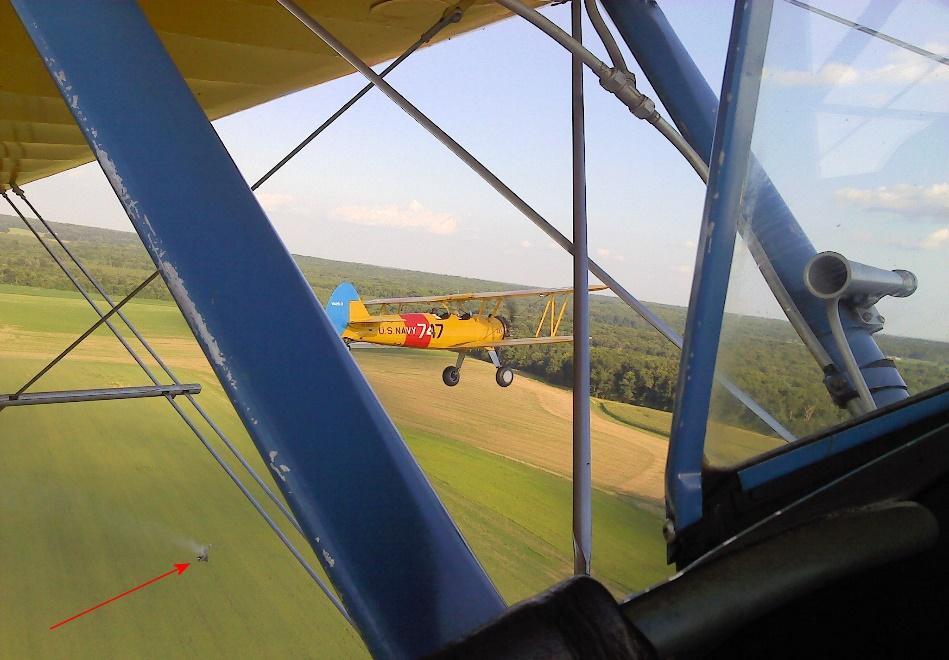
As initially equipped, the Boeing Stearman Model 75 came from the Wichita factory without an electrical system and radios. The original design objectives were simplicity, low cost, and ease of maintenance; goals that were successfully met in the Model 75. Each of those goals would have been compromised by the addition of an electrical system, so the Kaydet soldiered on through its WWII military service very well without them. However, as the Stearman moved from its second career as a sprayer to its current status as a warbird and historic reminder of an earlier era, requirements began to change. With each passing decade radio communication and navigation equipment became increasingly more necessary. Too, the romance of hand cranking an inertia starter faded for some operators as they encountered hard starting engines on hot days! The obvious answer was a charging system, an electric starter, and a radio.
In the 50s, 60s, and 70s, electric inertia starters and even direct drive E-80s were plentiful, and the installation was not complicated, so that was an easy fix for the starting problem. Radios were a little more problematic. As originally outfitted, the Continental W670s, Lycoming R680s, and Jacobs R755s on the Stearman came with unshielded ignition harnesses and spark plugs. Those ignition systems created huge amounts of electromagnetic radio noise, but that had not been an issue when there were no radios. However, when a radio was retrofitted into an aircraft with an unshielded ignition system, the radio was often unusable. Only when the engine was throttled back to an idle would the audible static come down to a level where anything could be heard. Something had to be done, and that something was a shielded ignition system.
Jacobs Engines
Interestingly, the Jacobs engine was the easiest to modify for radio shielding. Though only a handful of Jacobs powered PT-18s were made, tens of thousands of shielded ignition Jacobs engines were built for the Cessna UC-78 “Bamboo Bomber”. It was a simple matter to remove the unshielded ignition loom from the PT-18 and install a shielded one (or even a complete engine!) from a Cessna. Voila—problem solved!

Continental Engines
Many owners of Continental W670 powered Stearmans decided to use the same Jacobs/Bamboo Bomber shielded loom and conduits to provide shielded ignition for their aircraft. Special brackets had to be fabricated to support the harness loom and the loom did not fit the W670 nose case as nicely as it had on the Jacobs, but the system worked to shield radio noise. Naturally, this and all shielded ignition systems required that the unshielded spark plugs be replaced with shielded ones, and that the magneto blocks also be covered with radio shields.

Several years ago Radial Engines, Ltd developed a W670 shielded ignition system that works well and looks much more original to the W670 engine than the Jacobs retrofit. This new system utilizes the original W670 unshielded rear mounted loom tube with Skytronics 5105 shielded wire run in place of the earlier unshielded 7mm cables.

The only real visual difference between this and the original unshielded harness is the use of shielded spark plugs and their elbows. Though this new system is as effective at shielding radio noise as the retrofitted Jacobs system, it is much less expensive to manufacture (and therefore to purchase) than the Jacobs.
Lycoming Engines
As with other engines of their era, the earliest Lycoming R680 engines were also equipped with unshielded ignition systems.

However, by 1935 demand for radios were increasing, so Lycoming added optional radio shields to the accessories that could be installed on their engines. The first R680 ignition shields were low profile cast aluminum housings that covered the distributor caps on each side of the engine, and which had individual shielded wires routed to the spark plugs and magneto.
This system worked well, but was not produced in large quantities before the outbreak of WWII, but during that conflict tens of thousands of Lycoming R680 engines were produced to power the Boeing Stearman “Kaydet”, Beech AT-10 “Wichita, Stinson V-77, and the Curtiss AT-9 “Jeep”. Though the Stearman was usually equipped without radios and an electrical system, the AT-9, AT-10, and Stinson V-77s all were radio equipped. As such, shielded ignition systems were required so a new shielded system was designed for those applications.
The Problem
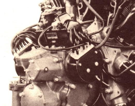
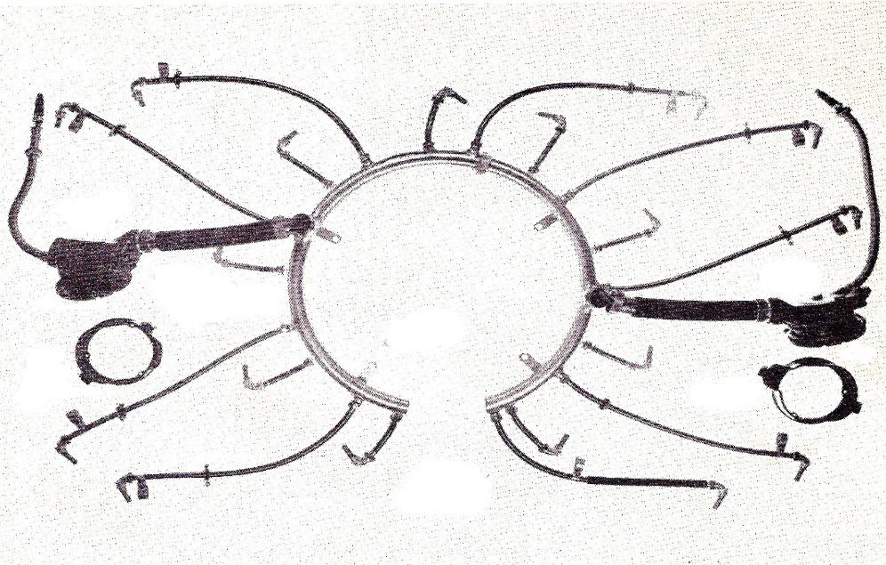
The WWII era ignition shields again were cast from aluminum alloy, but these new shields utilized a large braided brass conduit on each side to feed the spark plug wires forward to a brass ignition loom which was mounted behind the push rod tubes and in front of the cylinders. From the loom individual small braided brass conduits routed the 7mm spark plug wire out to the spark plugs. This system also did a good job of shielding radio noise, but at a cost: the ignition loom covered the front cylinder hold down studs and nuts. This made it impossible to retourque cylinder base studs without removing the rocker covers, push rods and tubes, and then pulling the loom forward to expose the nuts. Because this new harness discouraged servicing the cylinder base nuts, several instances have been recorded of the nuts losing their torque over time, cylinder studs breaking, and ultimately a cylinder departing the engine.
In addition to making servicing the base nuts much more difficult (recommended by the Lycoming Operator’s Manual to be done at 50 hours after an overhaul and every 100 hours thereafter), the WWII era harness also makes cylinder replacement a much larger project. When this style of shielded harness was retrofitted to a Stearman another drawback became obvious: its size. The WWII era system was designed to fit inside the large diameter engine mounting ring that was found on the AT-9, AT-10, and V-77. The Stearman mount ring is much smaller in diameter than those other models and these later distributor cap shields protrude out left and right from the engine more than the earlier cast shields did. The WWII era shields fit so tightly in the Stearman ring that they actually contact and rub against it. This makes servicing the distributors nearly impossible without pulling the engine forward out of the engine mount.


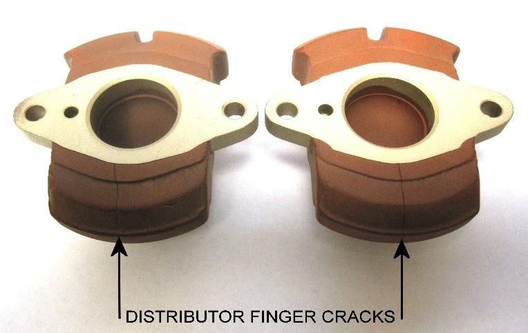
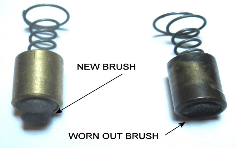
As a result of this difficulty, operators often put off servicing the distributors, something that is absolutely necessary for an easy starting and good running engine. The carbon brush in the distributor head wears down, oil mist will ultimately cover the inside of the distributor head, the electrodes wear, and occasionally the rotors develops cracks. All of these things contribute to a hard starting, rough running engine. Many Lycoming operators have resorted to installing a booster coil in an attempt to repair the hard starting problem. Often the high voltage booster coil will mask the issues which are being caused by a lack of maintenance and will actually make the engine easier to start. However, attempting to use a booster coil rather than giving the distributors the maintenance that they require is a lot like the old story of a dog with a wet nose. Everyone knows that a healthy dog has a cold, wet nose. So what do we do if our dog gets sick and develops a hot, dry nose? One option would be to put an ice cube on the dog’s nose. The dog will still be sick, but we have taken care of the symptoms. If the Lycoming distributors are not being maintained, a booster coil is just an ice cube on a sick dog’s nose.
The Solution
The obvious answer to installing a shielded ignition system on a Lycoming powered Stearman is to use the early style distributor shields with its individual leads coming directly from the shields. This casting has a lower profile than the WWII version and gives ample clearance in a Stearman mount to remove the distributor head and to service the distributors.

Also, since there is no front ignition loom, cylinder retourque, removal, and installation is straightforward. The only difficulty lies in the fact that there were only a few hundred of this style of shields made in the early 1930s, so locating original ones is nearly impossible. In forty years of overhauling these engines, we have only come across four or five of these early shields. However, while we had a set of the early distributor shields in our possession we reverse engineered the castings and now have a limited number of them available from which to build Lycoming shielded ignition systems.

When coupled with Skytronics 5105 shielded ignition wire, a Lycoming ignition system is recreated which fits well in the Stearman mount ring, provides good radio shielding, and makes cylinder service much easier. The kit comes complete with shields, new left and right distributor heads, wiring, and hardware. A port for installing a booster coil is machined into the right side distributor shield, though our experience has shown that with this system booster coils are unnecessary. For more information on any of the Continental, Jacobs, or Lycoming shielded ignition systems contact Caleb at Radial Engines, Ltd. 405-433-2263
In the Beginning
As initially equipped, the Boeing Stearman Model 75 came from the Wichita factory without an electrical system and radios. The original design objectives were simplicity, low cost, and ease of maintenance; goals that were successfully met in the Model 75. Each of those goals would have been compromised by the addition of an electrical system, so the Kaydet soldiered on through its WWII military service very well without them. However, as the Stearman moved from its second career as a sprayer to its current status as a warbird and historic reminder of an earlier era, requirements began to change. With each passing decade radio communication and navigation equipment became increasingly more necessary. Too, the romance of hand cranking an inertia starter faded for some operators as they encountered hard starting engines on hot days! The obvious answer was a charging system, an electric starter, and a radio.
In the 50s, 60s, and 70s, electric inertia starters and even direct drive E-80s were plentiful, and the installation was not complicated, so that was an easy fix for the starting problem. Radios were a little more problematic. As originally outfitted, the Continental W670s, Lycoming R680s, and Jacobs R755s on the Stearman came with unshielded ignition harnesses and spark plugs. Those ignition systems created huge amounts of electromagnetic radio noise, but that had not been an issue when there were no radios. However, when a radio was retrofitted into an aircraft with an unshielded ignition system, the radio was often unusable. Only when the engine was throttled back to an idle would the audible static come down to a level where anything could be heard. Something had to be done, and that something was a shielded ignition system.
Jacobs Engines
Interestingly, the Jacobs engine was the easiest to modify for radio shielding. Though only a handful of Jacobs powered PT-18s were made, tens of thousands of shielded ignition Jacobs engines were built for the Cessna UC-78 “Bamboo Bomber”. It was a simple matter to remove the unshielded ignition loom from the PT-18 and install a shielded one (or even a complete engine!) from a Cessna. Voila—problem solved!
Continental Engines
Many owners of Continental W670 powered Stearmans decided to use the same Jacobs/Bamboo Bomber shielded loom and conduits to provide shielded ignition for their aircraft. Special brackets had to be fabricated to support the harness loom and the loom did not fit the W670 nose case as nicely as it had on the Jacobs, but the system worked to shield radio noise. Naturally, this and all shielded ignition systems required that the unshielded spark plugs be replaced with shielded ones, and that the magneto blocks also be covered with radio shields.
Several years ago Radial Engines, Ltd developed a W670 shielded ignition system that works well and looks much more original to the W670 engine than the Jacobs retrofit. This new system utilizes the original W670 unshielded rear mounted loom tube with Skytronics 5105 shielded wire run in place of the earlier unshielded 7mm cables.
The only real visual difference between this and the original unshielded harness is the use of shielded spark plugs and their elbows. Though this new system is as effective at shielding radio noise as the retrofitted Jacobs system, it is much less expensive to manufacture (and therefore to purchase) than the Jacobs.
Lycoming Engines
As with other engines of their era, the earliest Lycoming R680 engines were also equipped with unshielded ignition systems.
However, by 1935 demand for radios were increasing, so Lycoming added optional radio shields to the accessories that could be installed on their engines. The first R680 ignition shields were low profile cast aluminum housings that covered the distributor caps on each side of the engine, and which had individual shielded wires routed to the spark plugs and magneto.
This system worked well, but was not produced in large quantities before the outbreak of WWII, but during that conflict tens of thousands of Lycoming R680 engines were produced to power the Boeing Stearman “Kaydet”, Beech AT-10 “Wichita, Stinson V-77, and the Curtiss AT-9 “Jeep”. Though the Stearman was usually equipped without radios and an electrical system, the AT-9, AT-10, and Stinson V-77s all were radio equipped. As such, shielded ignition systems were required so a new shielded system was designed for those applications.
The Problem
The WWII era ignition shields again were cast from aluminum alloy, but these new shields utilized a large braided brass conduit on each side to feed the spark plug wires forward to a brass ignition loom which was mounted behind the push rod tubes and in front of the cylinders. From the loom individual small braided brass conduits routed the 7mm spark plug wire out to the spark plugs. This system also did a good job of shielding radio noise, but at a cost: the ignition loom covered the front cylinder hold down studs and nuts. This made it impossible to retourque cylinder base studs without removing the rocker covers, push rods and tubes, and then pulling the loom forward to expose the nuts. Because this new harness discouraged servicing the cylinder base nuts, several instances have been recorded of the nuts losing their torque over time, cylinder studs breaking, and ultimately a cylinder departing the engine.
In addition to making servicing the base nuts much more difficult (recommended by the Lycoming Operator’s Manual to be done at 50 hours after an overhaul and every 100 hours thereafter), the WWII era harness also makes cylinder replacement a much larger project. When this style of shielded harness was retrofitted to a Stearman another drawback became obvious: its size. The WWII era system was designed to fit inside the large diameter engine mounting ring that was found on the AT-9, AT-10, and V-77. The Stearman mount ring is much smaller in diameter than those other models and these later distributor cap shields protrude out left and right from the engine more than the earlier cast shields did. The WWII era shields fit so tightly in the Stearman ring that they actually contact and rub against it. This makes servicing the distributors nearly impossible without pulling the engine forward out of the engine mount.
As a result of this difficulty, operators often put off servicing the distributors, something that is absolutely necessary for an easy starting and good running engine. The carbon brush in the distributor head wears down, oil mist will ultimately cover the inside of the distributor head, the electrodes wear, and occasionally the rotors develops cracks. All of these things contribute to a hard starting, rough running engine. Many Lycoming operators have resorted to installing a booster coil in an attempt to repair the hard starting problem. Often the high voltage booster coil will mask the issues which are being caused by a lack of maintenance and will actually make the engine easier to start. However, attempting to use a booster coil rather than giving the distributors the maintenance that they require is a lot like the old story of a dog with a wet nose. Everyone knows that a healthy dog has a cold, wet nose. So what do we do if our dog gets sick and develops a hot, dry nose? One option would be to put an ice cube on the dog’s nose. The dog will still be sick, but we have taken care of the symptoms. If the Lycoming distributors are not being maintained, a booster coil is just an ice cube on a sick dog’s nose.
The Solution
The obvious answer to installing a shielded ignition system on a Lycoming powered Stearman is to use the early style distributor shields with its individual leads coming directly from the shields. This casting has a lower profile than the WWII version and gives ample clearance in a Stearman mount to remove the distributor head and to service the distributors.
Also, since there is no front ignition loom, cylinder retourque, removal, and installation is straightforward. The only difficulty lies in the fact that there were only a few hundred of this style of shields made in the early 1930s, so locating original ones is nearly impossible. In forty years of overhauling these engines, we have only come across four or five of these early shields. However, while we had a set of the early distributor shields in our possession we reverse engineered the castings and now have a limited number of them available from which to build Lycoming shielded ignition systems.
When coupled with Skytronics 5105 shielded ignition wire, a Lycoming ignition system is recreated which fits well in the Stearman mount ring, provides good radio shielding, and makes cylinder service much easier. The kit comes complete with shields, new left and right distributor heads, wiring, and hardware. A port for installing a booster coil is machined into the right side distributor shield, though our experience has shown that with this system booster coils are unnecessary. For more information on any of the Continental, Jacobs, or Lycoming shielded ignition systems contact Caleb at Radial Engines, Ltd. 405-433-2263
.png)