


In the Beginning
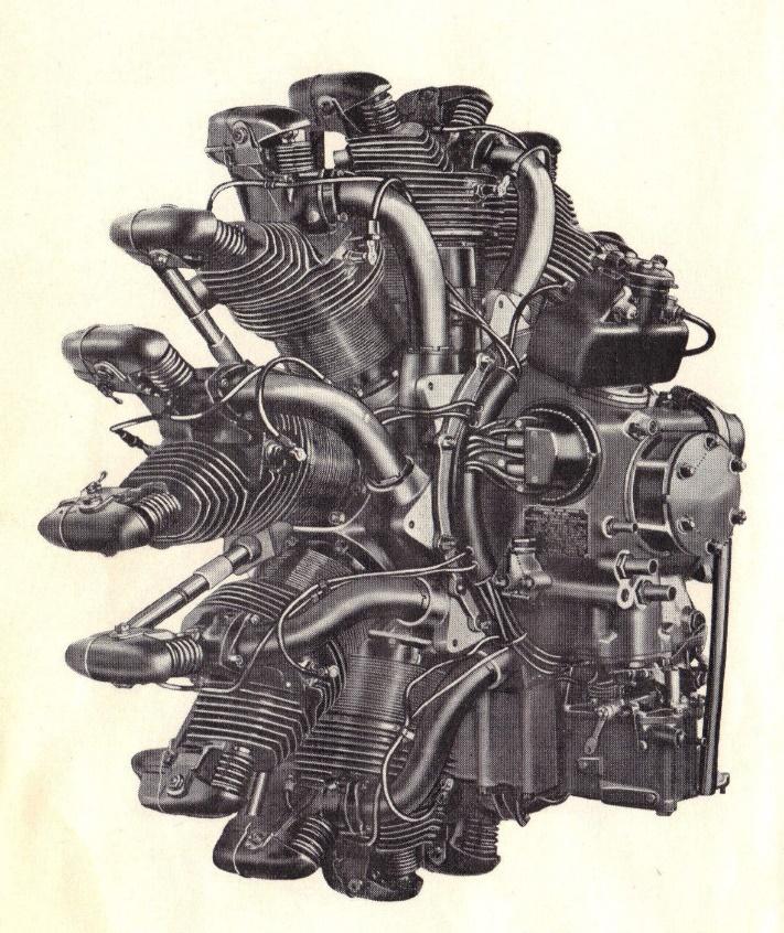
On February 4, 1930 first R680 Lycoming radial engine was granted Type Certificate No. 42 and was shortly thereafter installed on a Stinson SM8A. Like the few hundred R680s that would be produced before 1935, this first engine was equipped with an open, unshielded ignition harness (figure 1). Radio communication and navigation was in its infancy, so radio shielding was viewed by many as a luxury which added both expense and weight to the aircraft.
However, by 1935 demand for radios were increasing, so Lycoming added optional radio shields to the accessories that could be installed on their engines. The first R680 ignition shields were low profile cast aluminum housings that covered the distributor caps on each side of the engine, and which had individual shielded wires routed to the spark plugs and magneto (Figure 2).
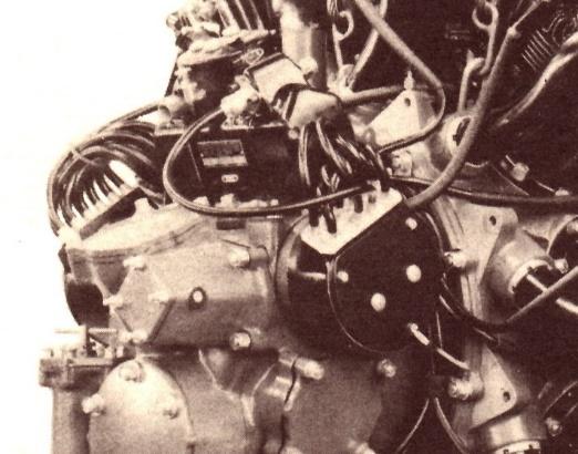
This system worked well, but was not produced in large quantities before the outbreak of WWII. As it did for other engine manufacturers, WWII elevated Lycoming from a small engine manufacturing company to a world class enterprise. Tens of thousands of Lycoming R680 engines were produced which powered the Boeing Stearman “Kaydet”, Beech AT-10 “Wichita, Stinson V-77, and the Curtiss AT-9 “Jeep”. Though the Stearman was usually equipped without radios and an electrical system, the AT-9, AT-10, and Stinson V-77s all were radio equipped. As such, shielded ignition systems were required so a new shielded system was designed for those applications (Figure 3).
The Problem
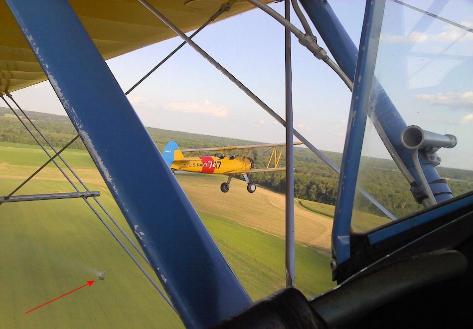
The new ignition shields again were cast from aluminum alloy, but these new shields utilized a large braided brass conduit on each side to feed the spark plug wires forward to a brass ignition loom which was mounted behind the push rod tubes and in front of the cylinders. From the loom individual small braided brass conduits routed the 7mm spark plug wire out to the spark plugs. This system also did a good job of shielding radio noise, but at a cost: the ignition loom covered the front cylinder hold down studs and nuts. This made it impossible to retourque cylinder base studs without removing the rocker covers, push rods and tubes, and then pulling the loom forward to expose the nuts. Because this new harness discouraged servicing the cylinder base nuts, several instances of the nuts losing their torque, cylinder studs breaking, and ultimately a cylinder departing the engine have been recorded (Note the smoking cylinder falling to earth in figure 4).
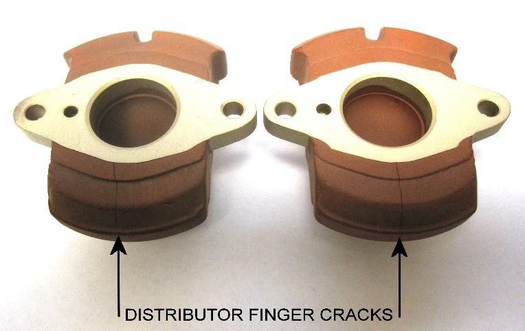
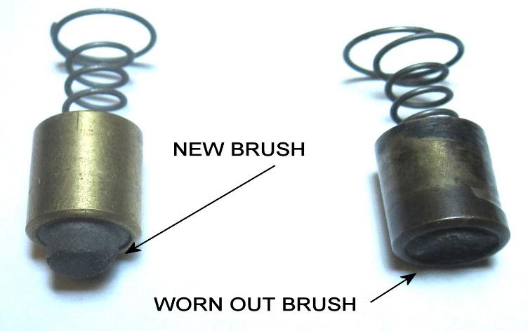
In addition to making servicing the base nuts much more difficult (recommended by the Lycoming Operator’s Manual to be done at 50 hours after an overhaul and every 100 hours thereafter), the new harness also makes cylinder replacement a much larger project. When this style of shielded harness was installed on a Stearman another drawback became obvious: its size. This new system was designed to fit inside the large diameter engine mounting ring that was found on the AT-9, AT-10, and V-77. The Stearman mount ring is much smaller in diameter than those other models and these later distributor cap shields protrude out left and right from the engine more than the earlier cast shields did. These shields fit so tightly in the ring that they actually contact the ring. This makes servicing the distributors nearly impossible without pulling the engine forward out of the engine mount. As a result of this difficulty, operators often put off servicing the distributors, something that is absolutely necessary for an easy starting and good running engine. The carbon brush in the distributor head wears down (Figure 5), oil mist will ultimately cover the inside of the head, the electrodes wear, and sometimes the rotor develops cracks (Figure 6). All of these things contribute to a hard starting, rough running engine.
The Answer
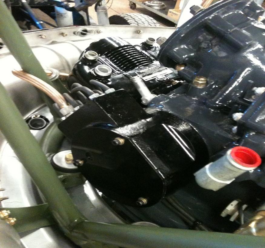
The obvious solution to installing a shielded ignition system on a Lycoming powered Stearman is to use the early style distributor shields with its individual leads coming directly from the shields. This casting has a lower profile than the WWII version, giving ample clearance in a Stearman mount to remove the distributor head & service the distributors. (Figure 7)
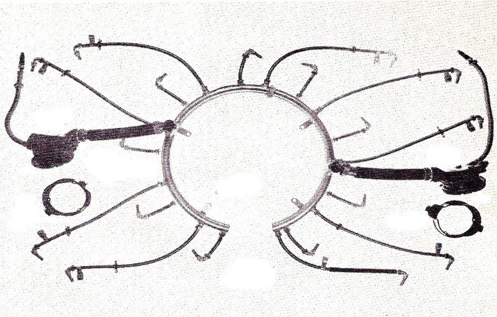
Also, since there is no front ignition loom, cylinder retourque, removal, and installation is straightforward. The only difficulty with this plan lies in the fact that there were only a few hundred of this style of shields made in the early 1930s, so locating original ones is nearly impossible. In forty years of overhauling these engines, we have only come across four or five of these early shields. However, while we had a set of the early distributor shields in our possession we reverse engineered the castings and now have a limited number of the complete systems available (Figure 8).
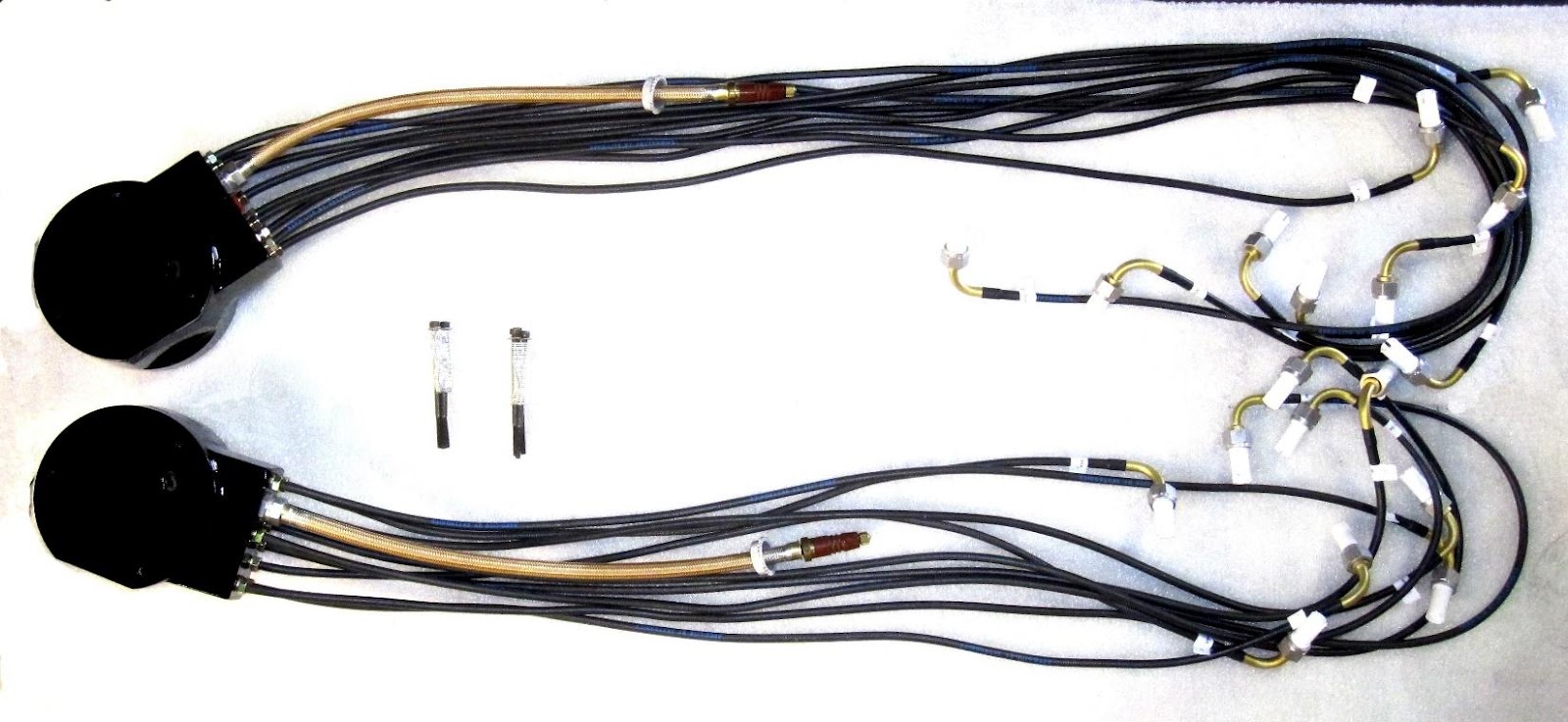
When coupled with Skytronics 5105 shielded ignition leads, this recreates a shielded ignition system which fits well in the Stearman mount ring, provides good radio shielding, and makes cylinder service much easier. The kit comes complete with shields, new left and right distributor heads, wiring, and hardware. For more information contact Caleb at Radial Engines, Ltd. 405-433-2263.
In the Beginning
On February 4, 1930 first R680 Lycoming radial engine was granted Type Certificate No. 42 and was shortly thereafter installed on a Stinson SM8A. Like the few hundred R680s that would be produced before 1935, this first engine was equipped with an open, unshielded ignition harness (figure 1). Radio communication and navigation was in its infancy, so radio shielding was viewed by many as a luxury which added both expense and weight to the aircraft.
However, by 1935 demand for radios were increasing, so Lycoming added optional radio shields to the accessories that could be installed on their engines. The first R680 ignition shields were low profile cast aluminum housings that covered the distributor caps on each side of the engine, and which had individual shielded wires routed to the spark plugs and magneto (Figure 2).
This system worked well, but was not produced in large quantities before the outbreak of WWII. As it did for other engine manufacturers, WWII elevated Lycoming from a small engine manufacturing company to a world class enterprise. Tens of thousands of Lycoming R680 engines were produced which powered the Boeing Stearman “Kaydet”, Beech AT-10 “Wichita, Stinson V-77, and the Curtiss AT-9 “Jeep”. Though the Stearman was usually equipped without radios and an electrical system, the AT-9, AT-10, and Stinson V-77s all were radio equipped. As such, shielded ignition systems were required so a new shielded system was designed for those applications (Figure 3).
The Problem
The new ignition shields again were cast from aluminum alloy, but these new shields utilized a large braided brass conduit on each side to feed the spark plug wires forward to a brass ignition loom which was mounted behind the push rod tubes and in front of the cylinders. From the loom individual small braided brass conduits routed the 7mm spark plug wire out to the spark plugs. This system also did a good job of shielding radio noise, but at a cost: the ignition loom covered the front cylinder hold down studs and nuts. This made it impossible to retourque cylinder base studs without removing the rocker covers, push rods and tubes, and then pulling the loom forward to expose the nuts. Because this new harness discouraged servicing the cylinder base nuts, several instances of the nuts losing their torque, cylinder studs breaking, and ultimately a cylinder departing the engine have been recorded (Note the smoking cylinder falling to earth in figure 4).
In addition to making servicing the base nuts much more difficult (recommended by the Lycoming Operator’s Manual to be done at 50 hours after an overhaul and every 100 hours thereafter), the new harness also makes cylinder replacement a much larger project. When this style of shielded harness was installed on a Stearman another drawback became obvious: its size. This new system was designed to fit inside the large diameter engine mounting ring that was found on the AT-9, AT-10, and V-77. The Stearman mount ring is much smaller in diameter than those other models and these later distributor cap shields protrude out left and right from the engine more than the earlier cast shields did. These shields fit so tightly in the ring that they actually contact the ring. This makes servicing the distributors nearly impossible without pulling the engine forward out of the engine mount. As a result of this difficulty, operators often put off servicing the distributors, something that is absolutely necessary for an easy starting and good running engine. The carbon brush in the distributor head wears down (Figure 5), oil mist will ultimately cover the inside of the head, the electrodes wear, and sometimes the rotor develops cracks (Figure 6). All of these things contribute to a hard starting, rough running engine.
The Answer
The obvious solution to installing a shielded ignition system on a Lycoming powered Stearman is to use the early style distributor shields with its individual leads coming directly from the shields. This casting has a lower profile than the WWII version, giving ample clearance in a Stearman mount to remove the distributor head & service the distributors. (Figure 7)
Also, since there is no front ignition loom, cylinder retourque, removal, and installation is straightforward. The only difficulty with this plan lies in the fact that there were only a few hundred of this style of shields made in the early 1930s, so locating original ones is nearly impossible. In forty years of overhauling these engines, we have only come across four or five of these early shields. However, while we had a set of the early distributor shields in our possession we reverse engineered the castings and now have a limited number of the complete systems available (Figure 8).
When coupled with Skytronics 5105 shielded ignition leads, this recreates a shielded ignition system which fits well in the Stearman mount ring, provides good radio shielding, and makes cylinder service much easier. The kit comes complete with shields, new left and right distributor heads, wiring, and hardware. For more information contact Caleb at Radial Engines, Ltd. 405-433-2263.
.png)